
Nexus Machine: An Energy-Efficient Active Message Inspired Reconfigurable Architecture
Active Messages Primer

Nexus Machine: An Energy-Efficient Active Message Inspired Reconfigurable Architecture Rohan Juneja, Pranav Dangi, Thilini Kaushalya Bandara, Tulika Mitra, and Li-Shiuan Peh MICRO'25
This paper presents an implementation of the Active Message (AM) architecture, as an alternative to FPGA/CGRA architectures. AM architectures have been studied for a while; this was my first exposure.
Spatial Computing
An accelerator implemented on an FPGA or CGRA typically uses a spatial computing paradigm. Each “instruction” in the algorithm is pinned to a physical location on the chip, and data flows between the instructions. I prefer to think of the data in motion as the local variables associated with threads that also move (using a specialized memory consistency model).
The active message architecture flips that script around. Data structures are pinned, while instructions move to the relevant data.
Active Messages
Fig. 5 shows two processing elements (PEs), each of which contain two active messages (AMs). An active message looks a lot like an instruction: it contains an opcode, source operands, and a result operand. Throughout the computation, AMs move between PEs. PEs have a local ALU and local memory.
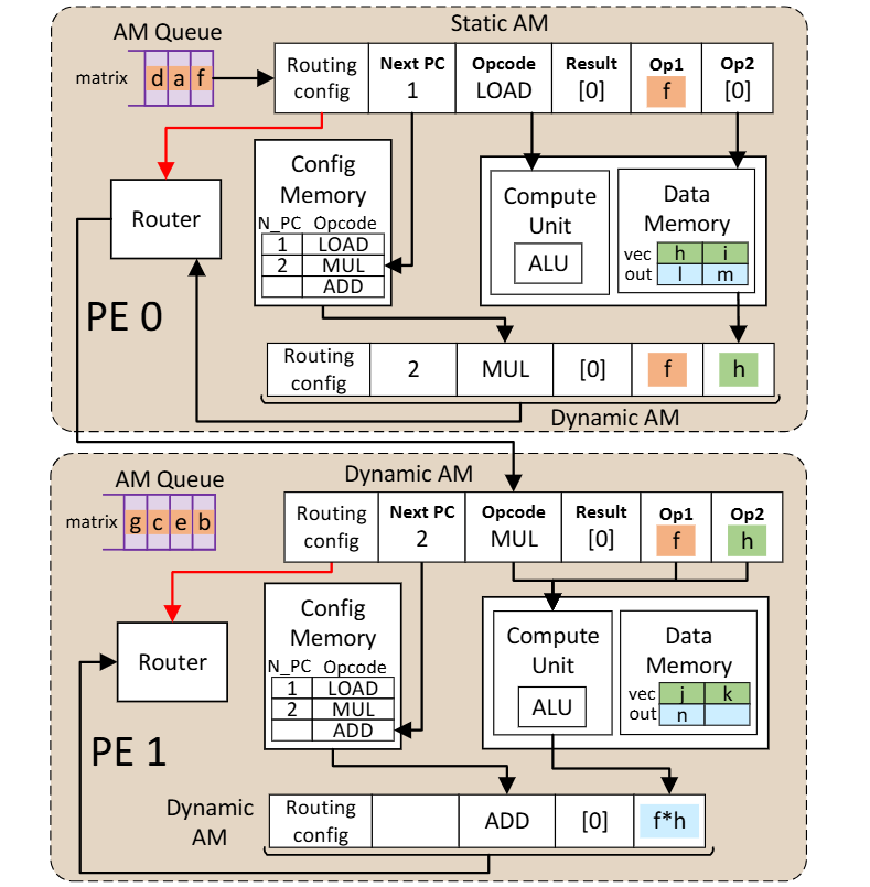
The AM at the top of the figure has Opcode=LOAD and Op1=f. Here, f is an operand that is being carried around for future use. The AM with a LOAD opcode will make its way through the chip until it arrives at the PE which contains the data to be loaded. At this point, the load operation will execute, and a new AM will be created. In the figure above, the new AM is the one at the bottom of PE0. It has Opcode=MUL, Op1=f, and Op2=h. Op1 is forwarded unchanged from the predecessor AM. The value of Op2 was the value of the data loaded from memory. The new opcode was obtained from the config memory, which contains a description of the program that is being executed.
The next step to be performed is to multiply f * h. One might expect PE0 to perform the multiplication, but in the figure above the AM is routed to PE1, which performs the multiplication. A reason why you would want to do this is in a situation where there are many AMs queued to access the data memory associated with PE0, but few AMs queued to access the data memory associated with PE1. In this situation, it is better to let PE0 perform loads for other AMs (because PE0 is the only PE that can fulfill that task) and find a PE that is currently idle to perform the multiplication (any PE can perform the multiplication).
Results
Now the question you should be asking is: what real-world applications exhibit load imbalances between PEs like this? If a data structure were split between all PEs evenly, you would think that load will be spread nicely across the PEs. The answer is: irregular workloads like sparse matrix-vector multiplication. Fig. 6 shows how a source matrix, source vector, and result vector could be partitioned across 4 PEs. You can imagine how the sparsity of the tensors being operated on would cause load imbalance between the PEs.
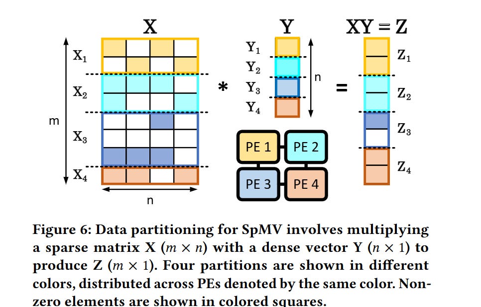
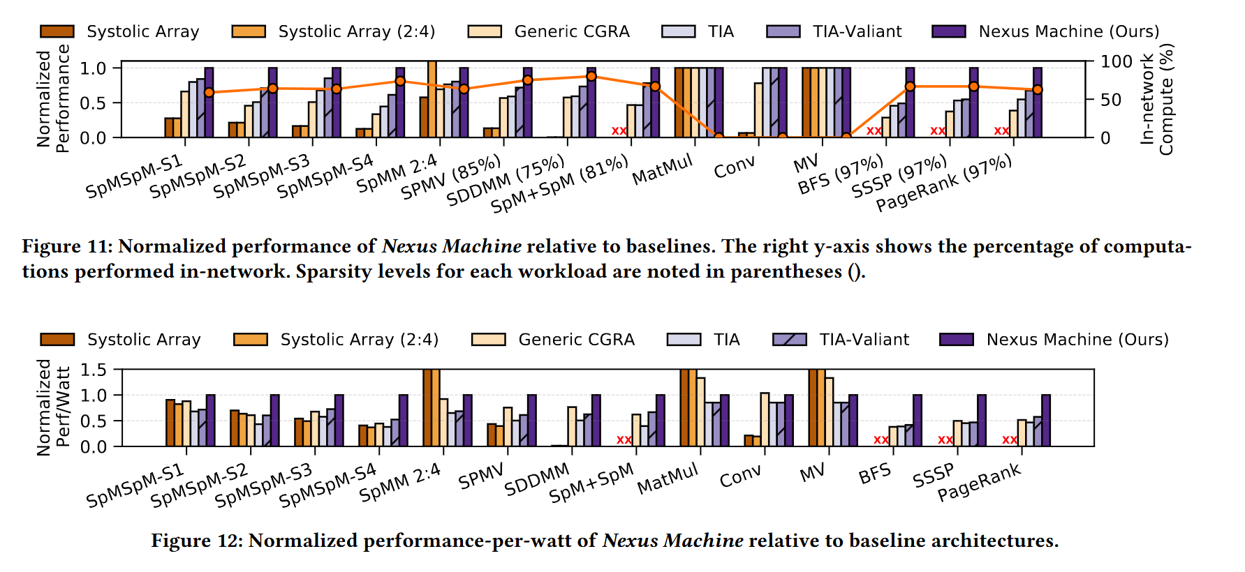
Fig. 11 compares the Nexus Machine against other architectures (each design has the same number of ALUs). Fig. 12 shows performance-per-watt.
Dangling Pointers
I imagine that AM architectures work best for algorithms that are insensitive to the order in which AMs are executed. That would be the case for matrix/vector multiplication (assuming addition is associative).
It seems like there is a large design space here related to PE capabilities. Data structures could be replicated across PEs to enable memory access AMs to be serviced by multiple PEs, or the ALUs inside of each PE could be heterogeneous (e.g., some PEs can do division, others cannot).