
TiNA: Tiered Network Buffer Architecture for Fast Networking in Chiplet-based CPUs
Sub-NUMA Clustering

TiNA: Tiered Network Buffer Architecture for Fast Networking in Chiplet-based CPUs Siddharth Agarwal, Tianchen Wang, Jinghan Huang, Saksham Agarwal, and Nam Sung Kim ASPLOS'26
Here we go again, another paper in a top-tier conference on the classic CS problem: how to DMA received packets from NIC to host. It would be interesting to understand why this is such a hot topic these days.
This paper deals with the case where the host CPU comprises multiple chiplets. If you get nothing else from this, I hope you will learn something about SNC mode (I had not heard of it before).
SNC
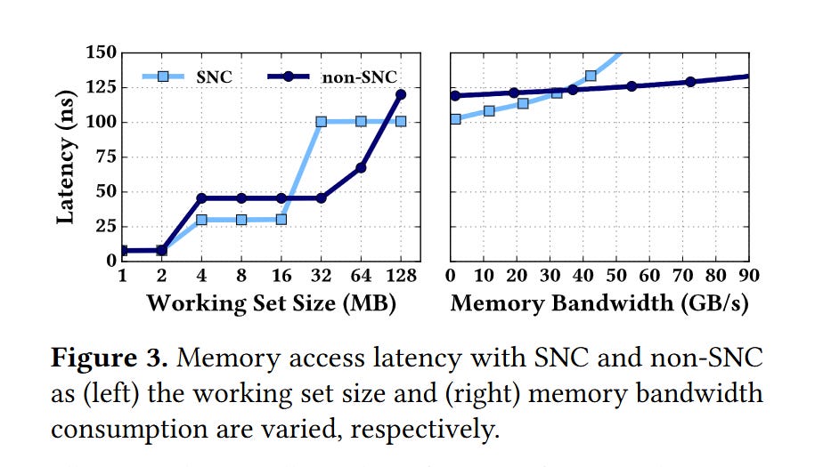
Recent Intel CPUs can be placed into Sub-NUMA Clustering mode (via a BIOS setting). This causes each chiplet to appear as a separate NUMA node. It is like a single socket CPU is transformed into a 4 socket CPU. The DRAM memory space is divided into four regions (one per chiplet), and the LLC slices within a chiplet only cache data from one memory space. This can be advantageous for some applications, because it can lower average LLC and DRAM access latency (by avoiding inter-chiplet communication). The downside is that the peak LLC capacity available to a single core is reduced. Fig. 3 illustrates these tradeoffs:
SNC and DDIO
Recall that DDIO is a feature of Intel CPUs that allows a NIC to write received packets directly into the LLC, which the host CPU can then read. PCIe lanes are distributed among chiplets. This means that the NIC is directly connected to one chiplet.
One way to support DDIO with SNC is to allocate buffers for received packets in the memory region associated with the chiplet that the NIC is connected to. This improves LLC bandwidth (for both the NIC and CPU cores) but decreases the LLC capacity available for network packets.
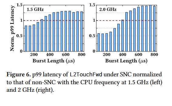
In practice, this means that longer bursts of network packets degrade performance more when SNC is enabled (i.e., leaky DMA is a larger problem in SNC mode). Fig. 6 has data from a microbenchmark to back this up:
TiNA
The solution proposed by this paper requires a change to the NIC/driver interface. Each ring buffer of received network packets is replaced by N ring buffers (where N is the number of chiplets). Ring buffer i is placed in the memory region associated with chiplet i.
The NIC knows about all of these ring buffers and dynamically decides which one to use. The NIC prefers to use the ring buffer associated with the chiplet that it is directly connected to. However, if a burst of traffic causes high utilization of the LLC capacity of that chiplet, then the NIC will fall back to using the other ring buffers.
The NIC estimates LLC utilization based on two competing rates:
The rate that received network packets are produced by the NIC
The rate that received network packets are consumed by the host
The first rate is easy for the NIC to compute as it knows how fast it is sending bytes to the host. The second rate is computed by networking software running on the host, and periodically sent to the NIC.
The overall approach reminds me of CEIO. The key difference is the set of memory segments available. CEIO uses NIC-local DRAM as the fallback path.
Packet Ordering
One complication of splitting a single ring buffer into multiple is ensuring that the host processes received packets in order. This paper proposes using sequence numbers associated with each packet. Most protocols already use per-packet sequence numbers. For other protocols (e.g., UDP), the NIC adds a sequence number based on the order in which packets were received.
When the host reads a packet from a logical ring buffer, it examines the sequence numbers from the packets at the head of each of the N physical ring buffers and chooses the packet with the lowest sequence number.
Results
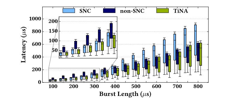
Fig. 9 has benchmark results: lower latency than SNC and non-SNC across a range of microbenchmarks.
Dangling Pointers
It would be nice if SNC allowed more fine-grained configuration. For example, there may be applications where ideal performance is achieved if each CPU core only has access to the L3 slice that is directly connected to it.